General information on construction, equipment, communications, etc.
Page Contents
- DEWLine Background Information
- DEWLine / North Warning System Transition
- Primary Surveillance and Communications Equipment.
- Station-to-Station Communication Links
- “Surestop” Tropo Upgrade by Clive Beckmann.
- 487L Survivable Low Frequency Communication System (SLFCS) By Clive Beckmann.
- 488L UHF “Greenpine” Low Frequency Communication System By Clive Beckmann
- Equipment & Operational Concept. An extract.
- Sites
- Alaska and the Aleutians
- Greenland: The DEW East Project.
Background
The Distant Early Warning (DEW) Line began on 15 February 1954 when President Eisenhower signed the bill approving the construction. It, was designed and built during the “Cold War” as the primary line of air defence warning of “Over the Pole” invasion of the North American Continent.
The actual construction of the 58 sites took place between 1955 and 1957. Many tons of supplies and equipment were moved to the Arctic by air, sea and river barge. One such carrier, the USAF 62nd Airlift Wing, moved over 13 million pounds of materiel in this monumental effort. The DEW Line was declared fully operational on 31 Jul 1957, (ref: USAF Museum “This week in Airforce History), and remained in operation for better than 30 years.
Construction Statistics
You will find some interesting DEWLine Construction Statistics here.
Transition
With the signing of North American Air Defence Modernization agreement at the “Shamrock Summit” between Prime Minister Mulroney and President Reagan in Quebec City on 18 March 1985 the DEW Line began it’s eventual upgrading and transition becoming the North Warning System (NWS) of today.
The North Warning System Office (NWSO), a joint Canadian/American effort, was initially staffed as an entity in late 1985 and early 1986. The first order of business was to start the competition process to determine who would be the Operations & Maintenance (O&M) Contractor of the new system. The North Warning System (NWS) began limited operation in 1988 with the commissioning and acceptance of the three newly constructed east coast sites BAF-3 Brevoort Island NUNAVUT, LAB-2 Saglek, and LAB-6 Cartwright both in Labrador. The bi-national North Warning System Office (NWSO) is located in Ottawa Canada and staffed with both Canadian and American military and civilian personnel. NWSO assumed command and control of the former DEW Line Long Range Radar (LRR) Stations in Canada in a Hand-over Ceremony held at Tuktoyaktuk NWT on 15 July 1993. The Short Range Radars (SRR’s) were installed later, The 36 NWS SRR’s achieved operational status between September 1990 and September 1992. The 3 Alaskan SRR’s achieved operational status in 1994. Those few DEW sites that weren’t transitioned to North Warning operation were eventually closed down.
Note: the North Warning System Office now falls under the auspices of the “Director General Aerospace Engineering Program Management (Radar & Communication systems) ” DGAEPM(R&CS)
The Primary Equipment
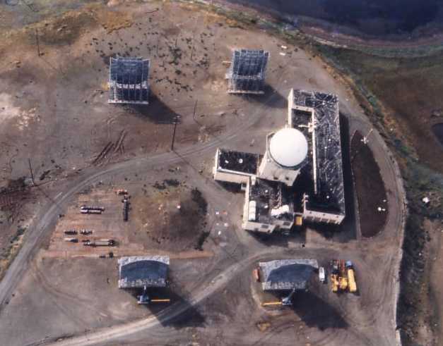
The Primary Search Radar for DEW Line sites in Canada and Alaska was the AN/FPS-19 (see photos 1 & 2 below). It was a magnetron type radar made by Raytheon. The AN/FPS-19 was a high power L-Band search radar consisting of two identical radar sets feeding a dual (back to back) antenna. Peak Power was 137 Kilowatts and Average Power 400 Watts. The Pulse Repetition Frequency (PRF) was 400HZ and Pulse Repetition Time (PRT) 2500 microseconds. Pulse Width (PW) was 6 sec. and the Duty Cycle 0.0024.
The AN/FPS-19’s were replaced by the “state of the art” AN/FPS-117 at those sites that became part of the North Warning System (NWS). The AN/FPS-117 was built by GE.
AN/FPS-19, photo 1. 1961.
AN/FPS-19, photo 2. 1961.
The Primary Search Radar for the 4 DEWLine sites in Greenland was the AN/FPS-30 (see photo below). Bendix built this long-range DEW-Line search radar that was originally termed the “Sentinel” radar. Once planned as a replacement for all AN/FPS-19 DEW-Line radars, the AN/FPS-30 was installed in 1961 only at the four Greenland “DYE” radar stations. It operated at 570 to 630 MHz. Its peak power was 150 kW, and its average power was 3 kW. The AN/FPS-30 radar’s pulse-repetition frequency (PRF) was specified as being 500 pulses/sec. but in reality, was most likely 385 pulses/sec. The antenna aperture was 45 ft. x 25 ft. The transmitter output tube was a Klyston with 62-dB gain (this Klystron power amplifier was later adapted for the Raytheon-built AN/FPS-28 frequency-diversity air-defense search radar). Source: Lincoln Laboratory Journal, Volume 12, Number 2.2000, page 193 and information provided by Radician Kurt Grumlose in 2015.
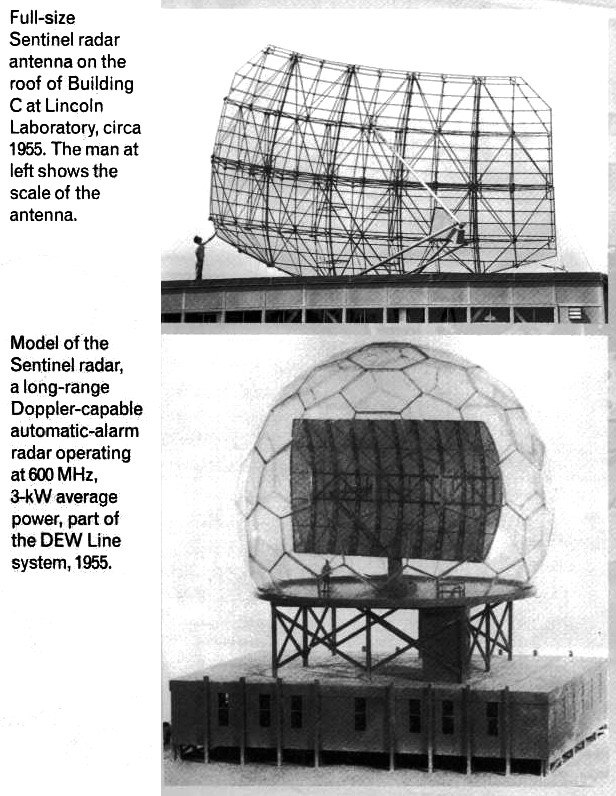
AN/FPS-30 Radar system installed at Greenland DEW sites.
The DEW Line “Gap Filler” was the AN/FPS-23 continuous wave “fluttar” (Doppler Effect) radar. (See photo below.)
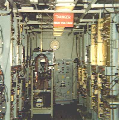
The AN/FPS-23 DEW-Line radar system was manufactured by Motorola, and operated at frequencies between 475 and 525 MHz, with 1 kilowatt of output power. AN/FPS-23 radars were continuous-wave (CW) systems that were comprised of geographically-separated AN/FPT-4 Fluttar Transmitters and AN/FPR-2 Fluttar Receivers. AN/FPT-4 Fluttar Transmitters were located only at Intermediate (“I”) Sites, while AN/FPR-2 Fluttar Receivers were located only at Main and Auxiliary Sites. The transmitters and receivers were typically about fifty miles apart. The function of this Doppler-effect detection system was to fill the low-altitude gaps between AN/FPS-19 radars located at Main and Auxiliary DEW-Line Sites. Description courtesy Online Air Defence Radar Museum
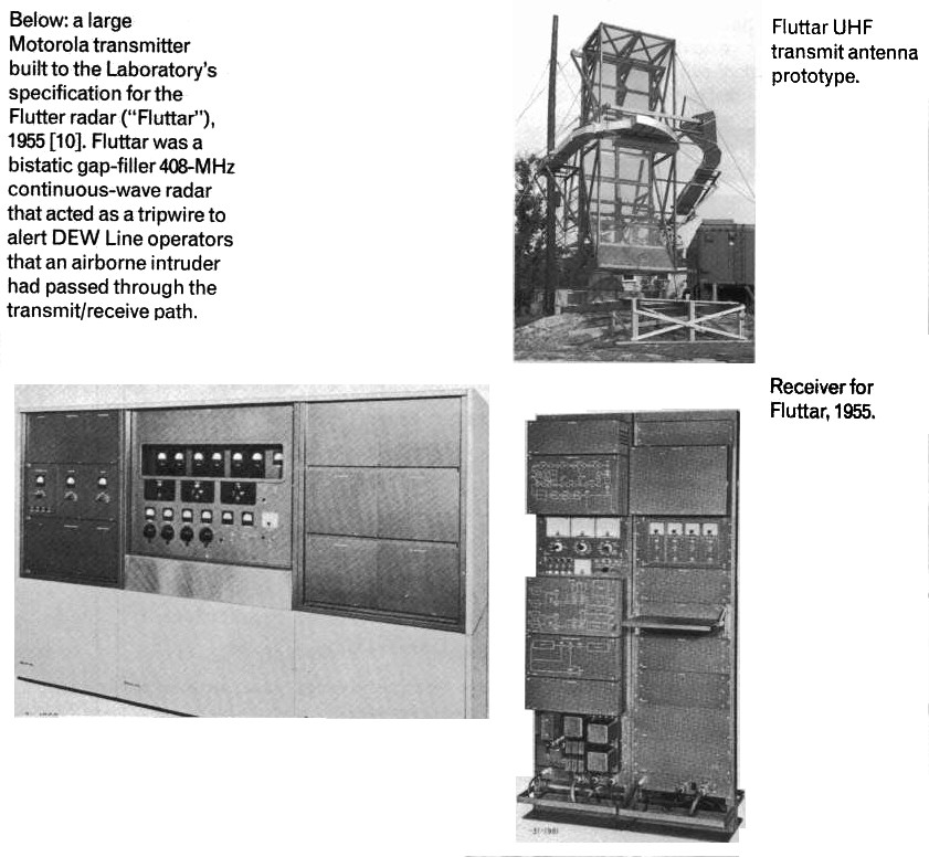
Dopplar (fluttar) radar systems at Intermediate sites (“I-sites”).
The North Warning “System Gap Filler” is the AN/FPS-124 UAR (UnAttended Radar) manufactured by Unisys.
LF Beacons at the AUX Sites were the FRC-37’s which had a power o/p of 50 Watts. At the “I” Sites, the beacon was the 329J and the power o/p is believed to be 35 Watts.
Station-to-Station Communications
The DEW Line’s station-to-station tropospheric scatter lateral (east to west) communication system in Canada and Alaska initially used the AN/FRC-45 produced by Collins Radio Corp. The AN/FRC-45 used “dual diversity” which made it subject to fading as atmospheric conditions changed so it was upgraded by the “Surestop I and Surestop II” programs. the new equipment was produced by Radio Engineering Labs (REL). The resulting equipment in Canada was named the AN/FRC-102. The fading problem was overcome by the use of “quad diversity”. In Greenland, the AN/FRC-39 was used. The AN/FRC-102 and AN/FRC-39 were both based on the MRC-98 exciters and parametric amps, the difference between the two being based on the choice of High Power Amps and multiplexer systems.
AN/FRC-102 Troposcatter System.
The vertical (north to south) communication system included the 100KW AN/FRC-101, a 515 nautical mile tropo scatter FM link between Hall Beach Canada and Thule AB Greenland, and the 612 nautical mile 10KW AN/FRC-47 CW drop between Cape Dyer Canada and Thule AB. These shots were among the longest single-hop tropospheric scatter shots used anywhere.
Surestop Tropo Upgrades
by Clive Beckmann
Surestop-I upgraded the old FRC-45 radios from Cape Dyer (DYE-M) to Cambridge Bay (CAM-M). Then, at a later date, Surestop-II continued the upgrade from CAM-M to Barter Island (BAR-M). This all happened prior to the big build-up in Viet Nam. Unfortunately, this military priority caused all the tropo radios being produced by Radio Engineering Labs (REL) to be siphoned off for shipment to the war zone. These radios were intended to be installed in Alaska as Surestop-III. Consequently, the Alaska DEW sites never had the old FRC-45 radios upgraded until the general upgrade in 1982-83 which replaced ALL tropo radios from LIZ-2 through DYE-5 and the NARS sites with a state-of-the-art REL system. Because the venerable FRC-45 provided marginal communications service during periods of heavy “fading”, a way was sought to provide better radios in the Alaskan sector. Someone came up with the bright idea of closing every other DEW site along the entire Line as a cost savings measure. A side benefit would be that the closed Canadian sites would each yield two Surestop terminals, enough to upgrade all the Alaskan sites. So FOX-1 was the first site designated for closure, along with POW-3. The Fox-1 radios were installed on the BAR-M west link and the POW-2 east link, thereby allowing closure of POW-3. This program was discontinued after FOX-1/POW-3 and I’ve never seen an official document that stated the reason why. I’ve heard rumors that some environmental entity had insisted that the closed sites be restored to pristine condition, meaning complete removal of all construction, leaving only gravel pads surrounded by tundra. This was projected to be so expensive that the Government decided it would be far cheaper to fund all existing sites for continued operation rather than continue to shut them down for cost savings.
487L, Survivable Low Frequency Communication System (SLFCS)
By Clive Beckmann
This was the LF comm system that ensured that SAC aircraft could be contacted in an environment that included nuclear detonations (which could render HF/VHF/UHF frequencies unusable). The equipment was located in SAC aircraft and at selected ground stations, including all Main DEW sites. As memory serves, SLFCS operated in the 20kHZ to 50kHZ band. Communication was one-way, i.e., SAC transmitted the messages and they printed out at the receive locations on a printer. The printers were known as the “thumpers” as the line feeds were loud enough to wake up the dead! Remote locations could not answer back. When DEW sites received traffic, the console operator would read the message (which was, 98% of the time, a test message that exercised the equipment) and acknowledged receipt by an entry in the console log. But sometimes actual SAC traffic would come in. When this happened, the console operator would immediately re-broadcast the traffic verbatim on both UHF frequencies (236.6 and 243.0 MHZ in AK). The SLFCS antenna was comprised of two large “loops” (about three feet in diameter) that were arranged 90 degrees to one another on the same axis. It was known as the “orange peel” antenna (kinda looked like a peeled orange and was orange in color) and sat outside on the ground near the surveillance room.
488L UHF Greenpine Communication System
By Clive Beckmann
This system was comprised of the land-line comm network that connected the SAC Command Post (Offutt AFB, Omaha) with the remote UHF sites, which included all Main sites in AK and Canada; the Greenpine switching console (located next to the DEW control consoles); and included the two UHF radios (236.6 and 243.0 MHZ in AK) installed at the DEW sites. The system also included the radio links between the SAC Airborne Command Post (Looking Glass) that somehow tied into the comm system that terminated at the DEW sites as described above. When SAC wished to broadcast traffic via the remote sites they would contact all NRCCs (NORAD Regional Control Centers) and NCCs (NORAD Control Centers). In AK, the NRCC was the ANRCC (AK NORAD Regional Control Center) at Elmendorf AFB, Anchorage, and the NCC was Murphy Dome AFS, not far outside of Fairbanks. Murphy Dome would then do a switch action that completed a circuit to illuminate a red lamp and activate a warbling tone on the Greenpine switching console. The DEW console operator would use a special handset to answer, e.g., “Barter Island Greenpine”. If the SAC operator wished to broadcast traffic he would request “all operational frequencies,” and the DEW console operator would do switch actions to give control of the 236.6 and 243.0 A/G transmitters to SAC. Then SAC would key the transmitters and begin the traffic broadcast which always started with “Skyking, Skyking, message follows…”, and then the coded traffic. At the conclusion of the transmission, you would hear, “SAC out”, which was the DEW console operator’s signal to restore the equipment to normal. The Greenpine antenna was a vertical UHF array that was enclosed in a cylindrical fiberglass radome that was approximately 20 inches in diameter by 8 feet in length. At AK and Canadian sites these antennae were usually mounted atop a 60 foot telephone pole. Sometimes SAC would do a roll call of all Greenpine sites. It was interesting to hear all the sites polled and the respective operators answering because they were at locations around the world
Equipment and Operational Concept
The following is an extract from “The History of AAC Jan – Jun 1956:
This vast undertaking looked to the erection and refurbishing of 6 main stations, 23 auxiliary stations, and 28 intermediate (fluttar) stations. The principal radar gear, positioned at main and auxiliary sites, was the AN/FPS-19 with “dual” antenna system. Two reflectors, placed back-to-back, created a double lobe (high and low angle coverage). Similarly, the two 12 inch PPI indicators offered a display of 360 degrees in azimuth, extending to a range of 160 nautical miles. The operator might select by manual control, range displays of 20, 40, 80, or 160 miles. The expanded “A” scope, in turn, covered a distance of 10 miles over 5 inches of display.
The automatic alarm of each radar consisted of 36 range gates, in groups of 6 guard bands, each of the latter covering an interval of 90 microseconds or a distance of 7.5 nautical miles. Any target appearing in either of these bands activated an audio alarm. Further, the gate alarm automatically tripped a scope camera which photographed the indicator for one complete sweep, thus giving a permanent record of the target.
A continuous barrier of CW radars (fluttars), operating in the 500 MHz range with a1000 watt power output, interconnected main and auxiliary stations. Designed to detect aircraft crossing at low altitude (50 feet over water), the dual-feed antenna system introduced signals through a series of audio filters. the latter then passed the frequencies which corresponded to the doppler frequency produced by the intruding aircraft. Targets from fluttar receivers were finally recorded on magnetic tape.
For the purpose of command and operational supervision, the arctic DEW Line was divided into an Eastern and Western sector. The partition point fell between Cambridge Bay (CAM) and Hall Beach (FOX) main stations precisely at Shepherd Bay. To the Alaskan air command devolved operational responsibility for the western portion of the line – – 40 installations in all, or 70 percent of the entire system; and to the Northeast Air Command, the eastern portion.
The overall concept hinged on two fundamental points: one, that the arctic radars were primarily detection units, the main stations to accept and process identification data; and two, that the line was not designed to perform intercept-destruction of aggressor aircraft nor were friendly aircraft programmed to aid in identification along the coast.
For efficient organization and operation, the two sectors were further divided into subsectors. Serving as a command post for its particular subsector, the main station would maintain control over two to four auxiliaries on either flank. Basic surveillance requirements dictated:
Each main station and its auxiliaries will serve as surveillance sites on a 24-hour a day basis. Track information from surveillance operators at auxiliary stations will be written by automatic message composers and transmitted to the associated main station by teletype. Messages will be handled sequentially on teletype writers at the main station. Track data may be told in GEOREF grid or in azimuth and range coordinates from auxiliaries to main. Main stations will plot, filter and tell directly to the command posts of the operating commands and to ADC by teletype.
The Sites
This link is to a list of sites in the high Arctic including those in Alaska, Canada and Greenland. Included are their DEW Line (or NWS) site nomenclatures and their Geographic Place Names. NB: DEW Sites are listed from west to east. Also included are the NWS site types,the operational start dates and DEW line stop dates or transition to North Warning System operation. NB: some sites, (LAB and BAF sites) were not part of the DEW Line radar system. ie LAB-2 and LAB-6 and BAF 5 were originally part of the “Pinetree Line” others, like BAF-3 (aka RES-X-1), were part of the “Pole Vault” tropospheric scatter communication system.
Alaska and the Aleutians
In addition to the sites listed in the following table, there were an additional 15 gap filler sites along Alaskan north coast. Also, between 1957 and 1959 the DEW Line was extended westward along the Aleutian Islands. Six sites equiped with the AN/FPS-19 Search Radar were constructed. Unlike the northern DEW sites that were operated by contractor, these sites were military manned. The Aleutian sites were located at Cold Bay, COB-Main ; Nikolski, COB-1; Driftwood Bay, COB-2; Cape Sarichef, COB-3; Port Moller, COB-4; and Port Heiden, COB-5 . The Aleutian DEW sites were deactivated 30 September 1969 except for Cold Bay which was converted to a NORAD surveillance site.
More information on the Alaskan DEW Line sites can be found here. North American Air Defence Online Radar Museum
Greenland: The DEW East Project
The DEW East project surveyed in 1957, led to the establishment of 4 DEW Line sites in Greenland. One on the west coast, one on the east coast and two on the icecap. The base of operations for the surveys was the ship “MV Arctic Sealer.
Some photos of the east and west survey sites. Also, the photo story of the construction of ICE-CAP 1 (DYE-1). By: Bill Lane